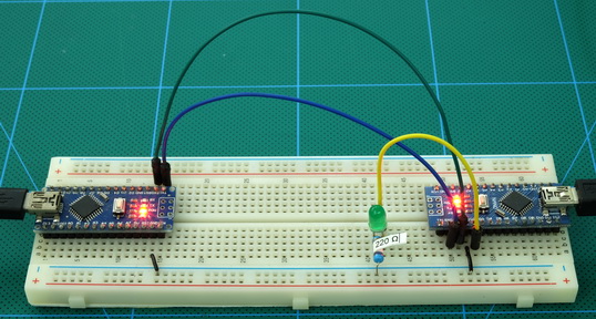
- #TEST SERIAL CONNECTION BETWEEN TWO ARDUINOS SERIAL#
- #TEST SERIAL CONNECTION BETWEEN TWO ARDUINOS CODE#
#TEST SERIAL CONNECTION BETWEEN TWO ARDUINOS SERIAL#
Next to put those values in the Serial Port connected with the RS-485 module, use the following statement Serial.println(potval) To read Analog value at the pin A0 of Arduino UNO and store them in a variable potval use: int potval = analogRead(pushval) īefore writing the potval value to serial port, pins DE & RE of RS-485 should be HIGH that is connected to the pin 8 of Arduino UNO so to Make pin 8 HIGH: digitalWrite(enablePin, HIGH) To Begin Serial Communication at Hardware Serial Pins (0,1) use: Serial.begin(9600) In the Master side, just simply take Analog input at pin A0 by varying the potentiometer and then SerialWrite those values to the RS-485 bus through the Hardware Serial Ports (0,1) of Arduino UNO. There are two programs in this tutorial, one for Arduino UNO (Master) and other for Arduino Nano (Slave). Here we are explaining important part of the code.
#TEST SERIAL CONNECTION BETWEEN TWO ARDUINOS CODE#
But make sure you have selected the corresponding PORT from Tools->Port and Board from Tools->Board.Ĭomplete code with a Demo Video is given at the end of this tutorial. Programming Arduino UNO & Arduino Nano for RS485 Serial Communicationįor programming both boards Arduino IDE is used. To potentiometer centre pin for contrast control of LCDĪ 10K potentiometer is connected to the Analog Pin A0 of the Arduino UNO for providing Analog input and a LED is connected to pin D10 of Arduino Nano. Two Arduino Boards are used here so two RS-485 Modules are required.Ĭircuit Connection between first RS-485 and Arduino UNO (Master):Ĭonnection between second RS-485 and Arduino Nano (Slave):Ĭircuit Connection between a 16x2 LCD and Arduino Nano: In this tutorial Arduino Uno is used as Master and Arduino Nano is used as Slave.


Let’s use the hardware serial ports of Arduino 0 (RX) and 1(TX) (In UNO, NANO). This RS-485 module can be easily interfaced with Arduino. All pins of chip have been lead to can be controlled through the microcontroller.A low power consumption for the RS485 communication.5Mbps.ĥV MAX485 TTL to RS485 module requires a voltage of 5V and uses 5V logic levels so that it can be interfaced with hardware serial ports of microcontrollers like Arduino. In half duplex mode it has a data transfer rate of 2. RS-485 is faster compared to I2C protocol.įor using RS-485 in Arduino, a module called 5V MAX485 TTL to RS485 which is based on Maxim MAX485 IC is needed as it allows serial communication over long distance of 1200 meters and it is bidirectional.Another advantage of the RS-485 is that it is immune to the noise as they use differential signal method to transfer.It can have a maximum of 32 devices connected to RS-485 protocol.The main advantage of RS-485 over RS-232 is the multiple slave with single Master while RS-232 supports only single slave.It transfers data up to 1200 meters maximum.


 0 kommentar(er)
